
Building Facades from 3D Laser Scanning — Drawings, Windows and Areas for Design
A multi-storey building without up-to-date drawings — we scanned it with a laser scanner and a drone and extracted all four facades with every window, sill and floor slab. The result is 3D facades, unfolded elevation drawings and net areas per facade for retrofit and design.
When a building is about to be retrofitted, converted or redesigned, the first thing missing is accurate facade drawings. Old designs rarely match what was built. That is why we survey the building with a 3D laser scanner and a drone and draw the facades from the point cloud as they really are — with every window, sill and slab.
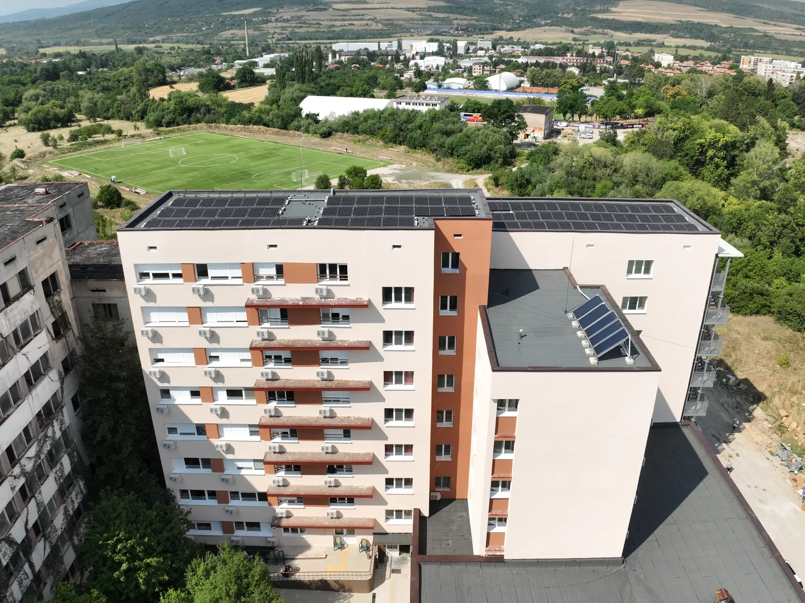
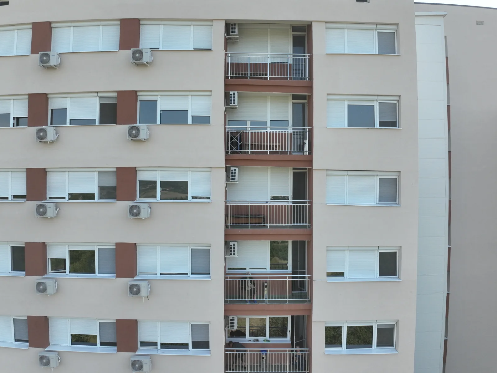
In short
- Site: a multi-storey building, about 41 × 48 m in plan and about 27 m high, with four facades.
- Survey: terrestrial 3D laser scanning and 758 drone photos on oblique and nadir flight paths.
- Extracted elements: facade outlines and floor slabs, all windows and doors, the sills — as 3D lines, separated by facade.
- Areas: net facade area (without openings) — about 2,957 m² in total.
- Deliverables: 3D drawing, unfolded elevations in DWG, an area table and a model for the designer.
How the work is done
- Scanning. The laser scanner captures the building from several stations around it — millions of points with millimetre-level accuracy.
- Drone photos. The roof and upper floors, which cannot be seen from the ground, are captured by drone on oblique paths.
- Registration. The scans are merged into one point cloud in a single coordinate system; the drone photos complete the roof and the upper floors.
- Facade extraction. On the cloud we draw the outlines, slabs, all windows, doors and sills — each facade on its own layer.
- Unfolding and areas. The facades are “unfolded” into a plane, the openings are subtracted and the net areas are calculated.
- Model for the designer. If needed, we also deliver a 3D model with walls and windows, ready for designing the new facade.
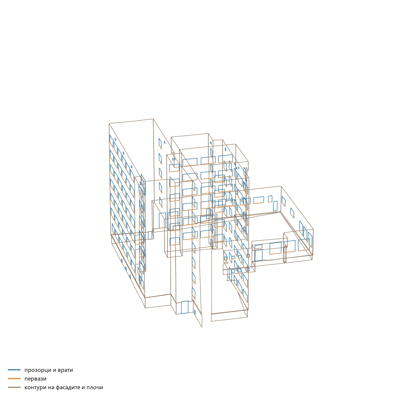
The facades in 3D
The extracted elements are 3D lines lying exactly on the building walls. The whole building can be seen at once, including wings, recesses and loggias, and dimensions can be taken directly from them.
Unfolded facades and areas
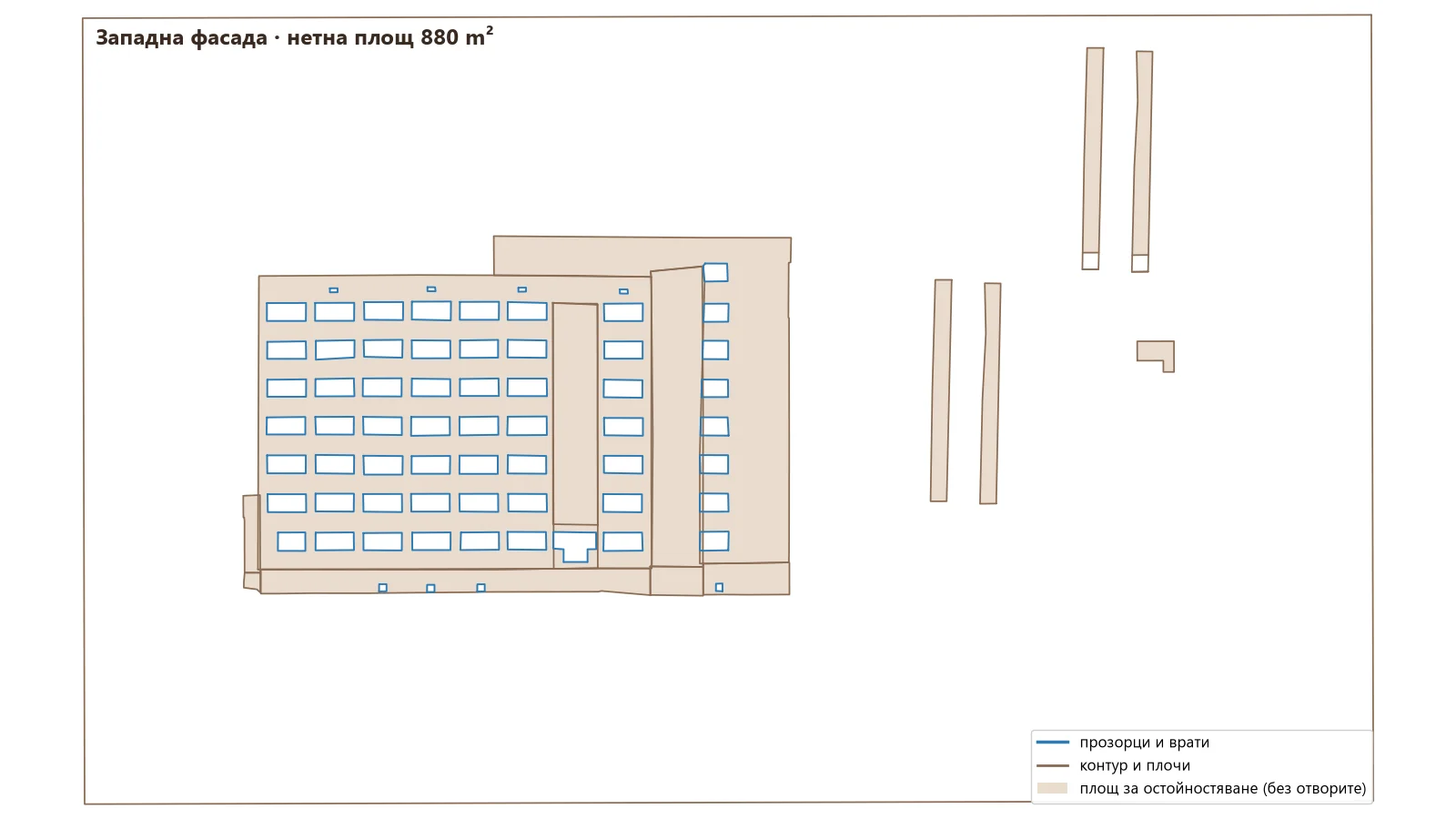
For quantity calculations each facade is unfolded into a plane. The hatched area is the facade without windows and doors — exactly what is priced for insulation, render or cladding. The side walls of the loggias are unfolded separately so that nothing is missed.
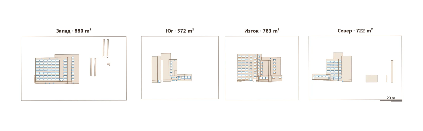
| Facade | Net area (without openings) |
|---|---|
| West | 880 m² |
| East | 783 m² |
| North | 722 m² |
| South | 572 m² |
| Total | ≈ 2,957 m² |
What it is used for
- Retrofit and thermal insulation — exact areas for bills of quantities and quotes, no guesswork.
- Design of a new facade — the architect works on the real geometry with the real window sizes.
- Window replacement — dimensions of every window before ordering.
- Conversion and legalisation — when there are no up-to-date drawings of the building.
- Construction control — comparing what was built with the design.
What you receive
| Result | Format |
|---|---|
| Point cloud of the building | RCP / E57 / LAS |
| 3D facade drawing — outlines, slabs, windows, sills | DWG |
| Unfolded facades with hatched net areas | DWG, PDF |
| Area table per facade | XLSX / PDF |
| 3D model with walls and windows (on request) | as required by the designer |
| Drone photos and facade ortho-images | JPG / TIFF |
Frequently asked questions
Why not just measure with a tape?
For one room — you could. For a 2,900 m² facade with loggias and dozens of windows, manual measuring is slow, dangerous at height and almost always misses something. Scanning captures everything at once, and dimensions are checked later in the office without another site visit.
Do we need access to every apartment?
No. The facades are captured from outside — with a scanner from the ground and a drone for the upper floors and roof.
How accurate are the areas?
The areas are calculated from the geometry drawn on the point cloud, so they match what was built rather than the old design. When needed, we check individual dimensions with a total station too.
Have a building to survey?
Send us the address, a photo of the building and what you need the drawings for — retrofit, design or window replacement. We will propose a survey scheme and a timeline. Send an inquiry or see the 3D laser scanning service. See also how we measure tank bottom flatness with the same technology.
The project at a glance, with photos: Facades of a Multi-Storey Building — 3D Laser Scanning and Drone. More completed work — in Projects.
Author: GM Engineering