
Balgarska Armia Stadium — 3D Laser Scanning of the Facade Steel Structure
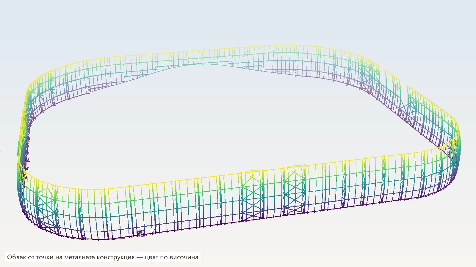
The facade steel structure of the Balgarska Armia stadium is a ring about 570 m long with ribs over 18 m tall. We set out mounting marks, scanned the structure at every stage of erection and delivered data for fabricating the facade. After fabrication the mismatch is 2 mm.
The facade of the new Balgarska Armia stadium in Sofia’s Borisova Gradina park sits on a steel structure. It is a closed ring with rounded corners, about 570 m long, with ribs over 18 m tall. The cladding is fabricated in a workshop to size, so the facade elements must fit the structure as erected, not as designed. Our job was to provide that link with 3D laser scanning and survey control.
In short
- Site: the facade steel structure of the Balgarska Armia stadium, Sofia.
- Tasks: 3D laser scanning, setting-out (mounting) marks, monitoring mismatches in the steel structure and data for facade fabrication.
- Scans: 8 surveys from April 2025 to January 2026, at every stage of erection.
- Point cloud: 11.4 million coloured points; perimeter about 570 m, height 18.3 m, about 220 vertical ribs.
- Result: after scanning and fabrication the mismatch in the steel facade is 2 mm.
What we had to do
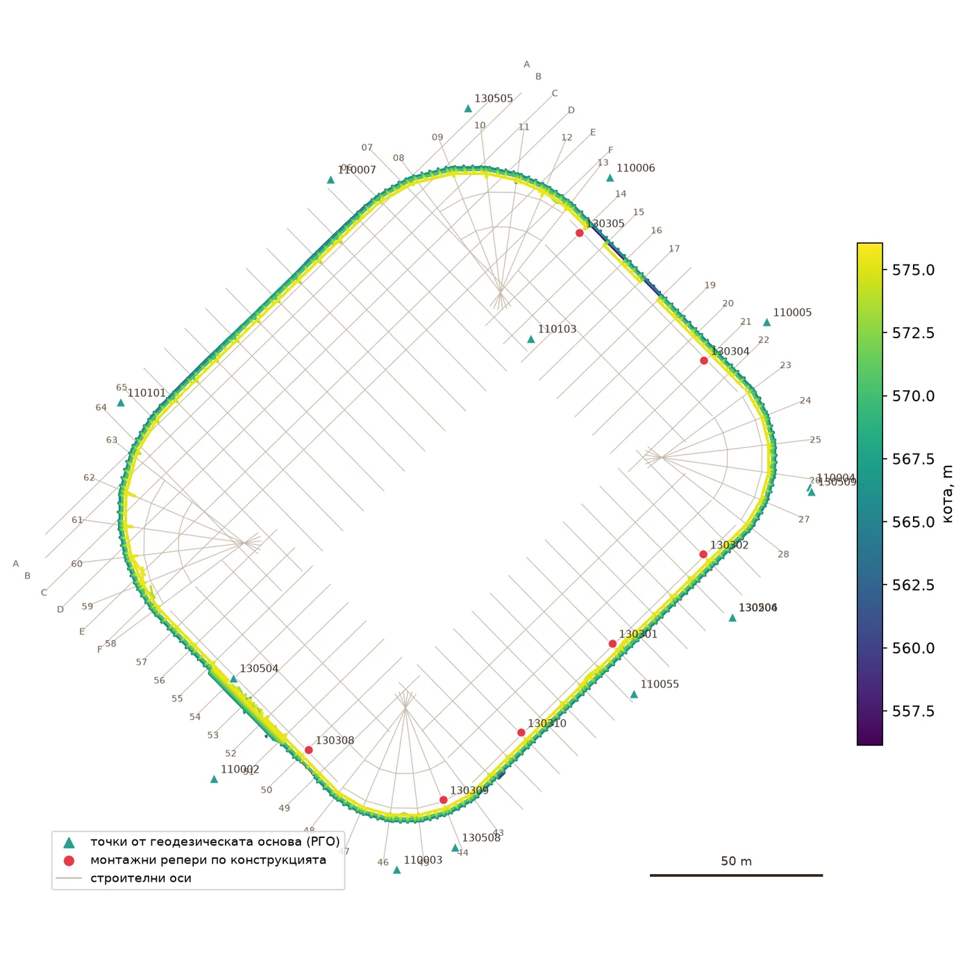
- Mounting marks. We set out and measured marks in the project coordinate system, around the stadium and on the structure itself.
- 3D laser scanning of the steel structure at every stage of erection.
- Mismatch monitoring. We compare the scanned structure with the setting-out axes and the design and report deviations while they can still be fixed.
- Facade fabrication data. From the final point cloud we deliver the real geometry the facade elements are fabricated to.
Mounting marks and setting-out axes
Everything starts from the survey control. The control points around the stadium and the mounting marks on the structure are in one system with the setting-out axes, so every scan, every erector and every drawing refers to the same coordinates. The mounting marks on the structure are at an elevation of about 565 m, some 8 m above its base.
Scanning at every stage
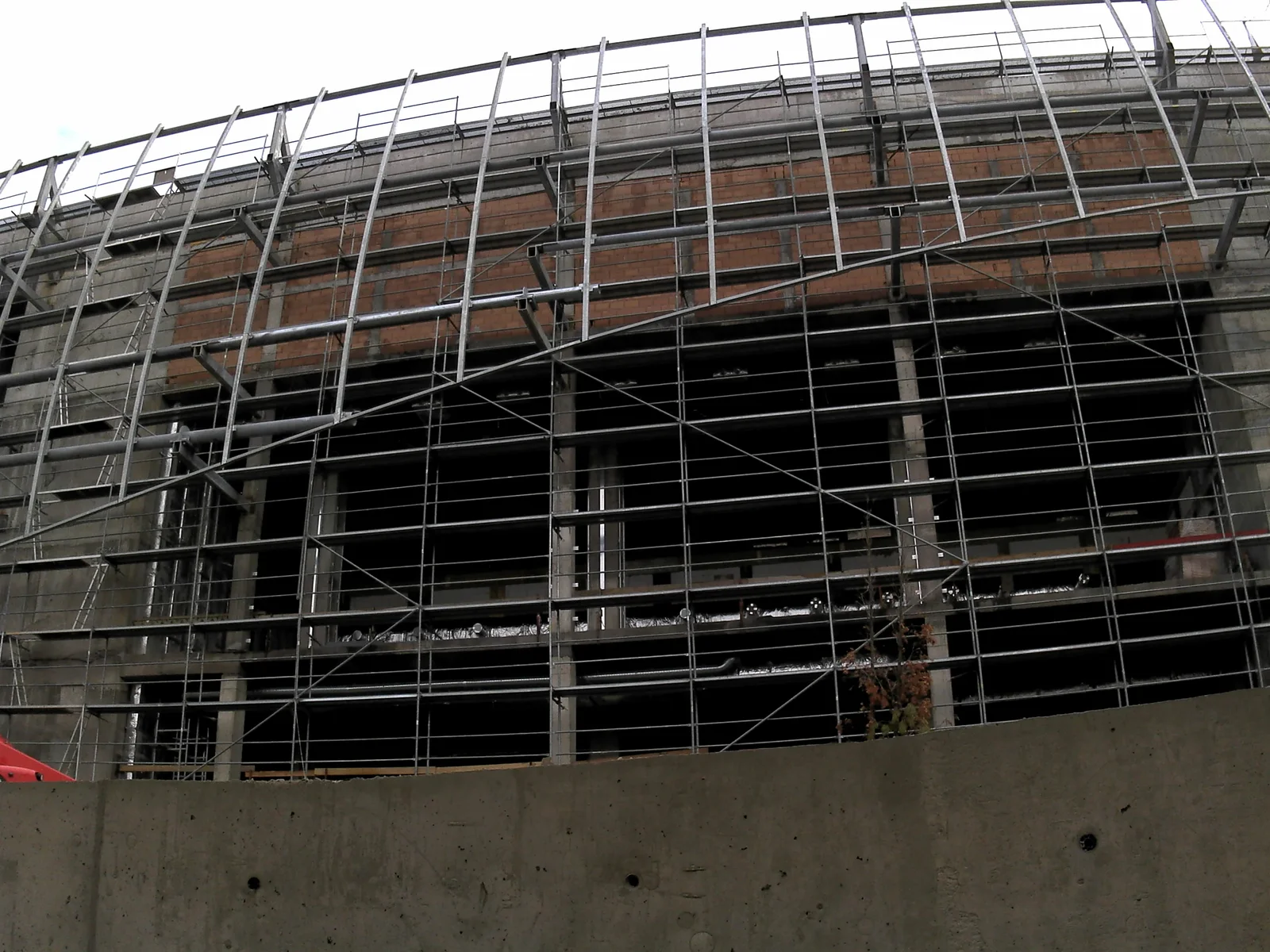
The steel structure was erected in sections, so we scanned it repeatedly — each time a new part was erected or a mismatch was suspected. Every scan is tied to the same survey control and overlaid with the setting-out axes.
| Date | Scan |
|---|---|
| 29.04.2025 | Steel structure |
| 06.06.2025 | Steel structure |
| 25.07.2025 | Steel structure |
| 09.09.2025 | Facade and building — delivery of facade data |
| 17.11.2025 | Steel structure |
| 26.11.2025 | Steel structure and building facade |
| 17.12.2025 | Steel structure |
| 16.01.2026 | Steel structure with the facade |
The point cloud up close
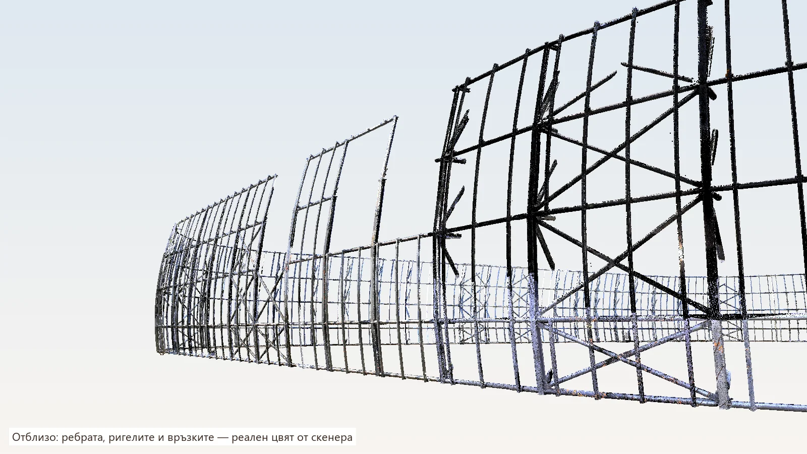
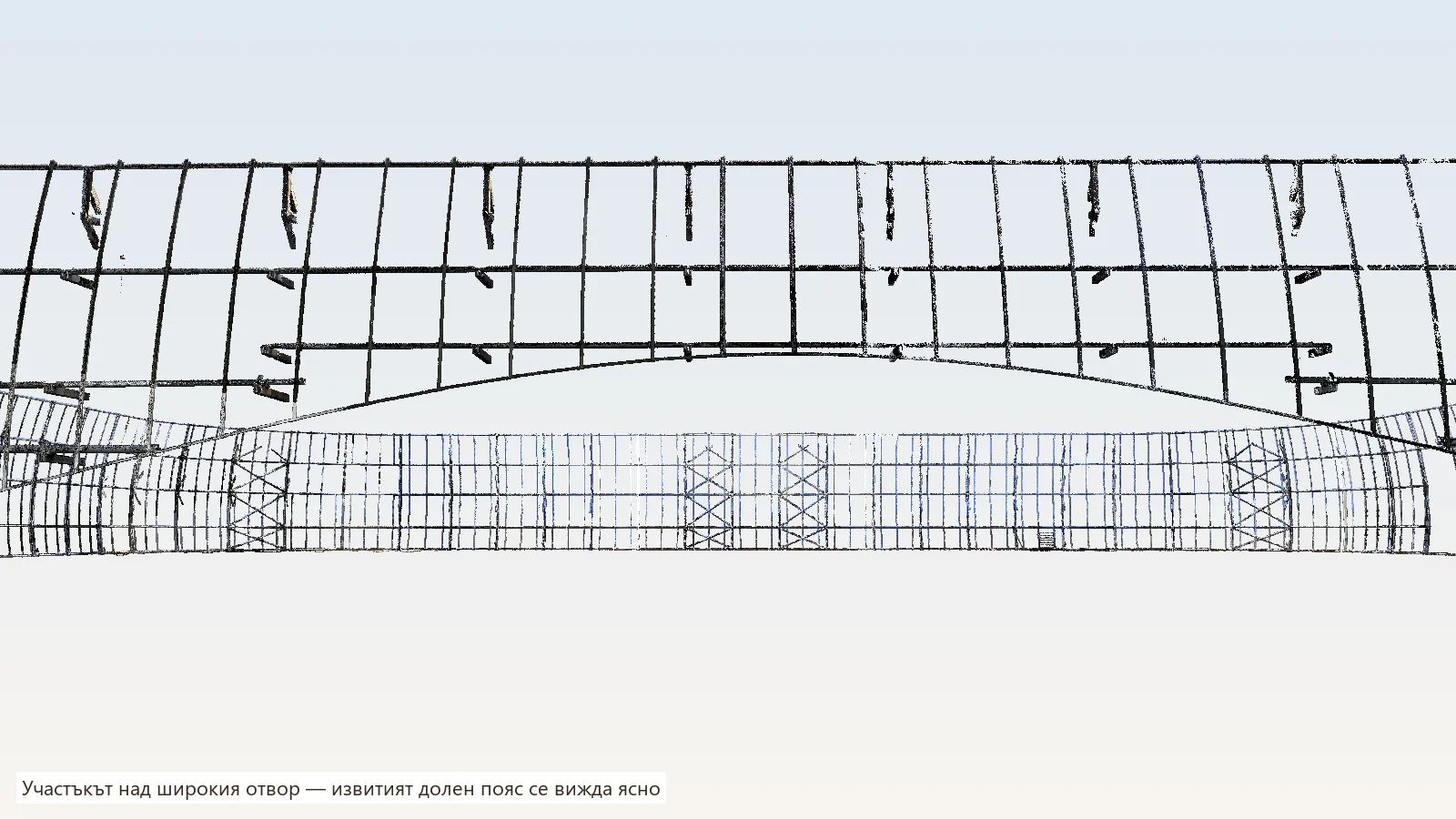
The cloud shows every member — the vertical ribs, the horizontal rails, the cross bracing and the cladding brackets. The position of every member is measured from it without anyone climbing the structure.
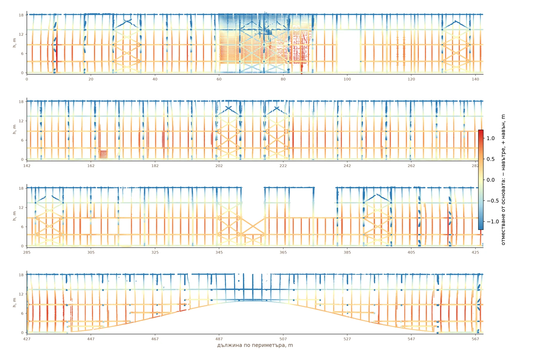
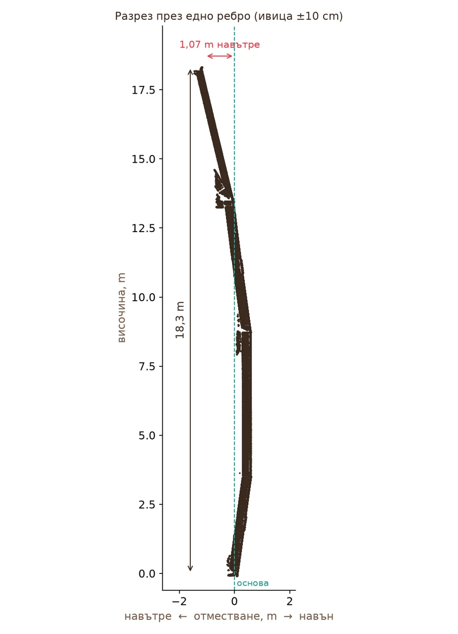
Unrolled facade and a section through a rib
To see the whole structure at once, the ring is “unrolled” into a plane: horizontally the length along the perimeter, vertically the height. Colour shows how far each member sits outward or inward from the base. Ribs, rails, bracing and openings along all 570 m are visible at a glance.
The section through one rib shows its shape: at the bottom it steps outward, in the middle it is vertical, and above about 9 m it leans inward — by about 1.1 m at the top. This geometry defines the shape of every facade element, so it has to be known accurately for every rib.
Mismatches — found while they can be fixed
A steel structure is almost never erected exactly as designed: welds, member tolerances and erection accumulate deviations. If the facade is fabricated to the design, these deviations only show up when the cladding is installed — when fixing them costs the most.
After every scan we overlay the cloud with the setting-out axes and check the position of the ribs and rails. Mismatches are reported to the erectors immediately, with location and size, so they are corrected while the structure is still being erected.
Facade fabrication data
From the final point cloud we deliver the real geometry of the structure — the position of the ribs, the rails and the cladding support points. The facade elements are fabricated to these dimensions, not to the design.
The result: after scanning and fabrication the mismatch in the steel facade is 2 mm.
What the contractor receives
| Result | Format |
|---|---|
| Coordinates of the survey control and mounting marks | TXT / DWG |
| Point cloud from every scan, in project coordinates | RCP / LAS / E57 |
| The cloud overlaid with the setting-out axes | DWG |
| Deviations of the structure after every scan | DWG / PDF |
| Real geometry of the structure for facade fabrication | DWG / point cloud |
Frequently asked questions
Why scan rather than measure with a total station?
A total station measures individual points that someone has to choose in advance. The scanner records the whole structure at once — millions of points. Back in the office any member can be checked, including ones nobody thought of on site.
How often should the structure be scanned during erection?
It depends on the pace of erection. Here we scanned 8 times in about 9 months — after every significant stage and always before delivering fabrication data.
What are mounting marks?
Points with known coordinates placed on or next to the structure. Erectors align the members to them and surveyors tie the scans to them, so everyone works in one coordinate system.
The stadium today
The stadium has now opened. A photo of the finished stadium: “Етюд-и-те на София / Sketches of Sofia” on Facebook.
Have a steel structure to control?
Send us the design and the erection schedule. We will propose mounting marks, a scanning schedule and a format for the fabrication data. Send an inquiry or see the 3D laser scanning service. See also how we extract building facades from a point cloud.
The project at a glance, with photos: Balgarska Armia Stadium — Facade Steel Structure. More completed work — in Projects.
Author: GM Engineering